
FLOW MEASUREMENT
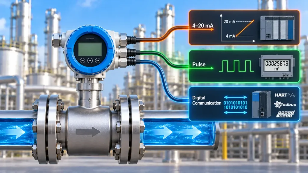
Flow meters can provide several types of output signals depending on the application and control system. Common options include 4–20 mA, pulse, frequency and digital communication.
Understanding these outputs helps engineers choose the right connection method for PLCs, DCS, SCADA systems, totalizers and other industrial automation equipment.
Flow Meter Signal Outputs
Flow Meter Signal Outputs transmit the measured flow value from the instrument to a control system, display, totalizer or monitoring device. The most common options include 4–20 mA, pulse or frequency signals and digital communication protocols.
What Are Flow Meter Signal Outputs?
A flow meter measures a process variable and converts that measurement into an electrical signal that another device can interpret. Depending on the meter, the output may represent instantaneous flow rate, totalized flow or additional diagnostic and process information.
4–20 mA
An analog current signal commonly used for transmitting flow rate to PLC and DCS analog input cards.
Pulse / Frequency
A pulse or frequency signal can represent flow rate or accumulated volume, particularly in applications using totalizers.
Digital Communication
Digital protocols can transmit process values, diagnostics, configuration information and other device data.
4–20 mA Flow Meter Output
The 4–20 mA signal is one of the most widely used analog outputs in industrial instrumentation. The current normally represents a defined measurement range, with 4 mA corresponding to the lower range value and 20 mA corresponding to the upper range value.
4–20 mA Output Formula
mA = 4 + 16 × [(Flow − LRV) ÷ (URV − LRV)]
LRV = Lower Range Value | URV = Upper Range Value
Example: Flow to 4–20 mA
Suppose a flow meter is configured for 0 to 100 m³/h. If the measured flow is 50 m³/h:
mA = 4 + 16 × (50 ÷ 100)
Output = 12 mA
Therefore, 12 mA represents 50% of the configured measurement range.
For more details on current-loop operation and calculations, see 4 to 20 mA Current Loop Explained on InstrumentationBlog.
Why Is 4–20 mA Commonly Used?
The 4–20 mA signal is popular because it provides a standardized analog representation that is easy to integrate with industrial control systems.
- Widely supported by PLC and DCS analog input cards.
- Suitable for long-distance industrial signal transmission.
- Less affected by voltage drop than a voltage signal when properly designed.
- The live zero at 4 mA helps distinguish a valid zero measurement from a broken loop.
- Can be combined with digital communication such as HART.
Did You Know?
A 4 mA signal normally represents 0% of the configured measurement range, while 0 mA can indicate a power, wiring or transmitter fault depending on the instrument and system configuration.
Pulse Output From a Flow Meter
A pulse output provides discrete electrical pulses related to the measured flow. The number of pulses can represent accumulated volume, while pulse frequency can be used to determine instantaneous flow rate.
Pulse outputs are particularly common with turbine and other flow meters that generate a frequency signal from the sensing element.
Pulse-Based Flow Calculation
Flow Rate = Pulse Frequency ÷ K-Factor
The exact calculation depends on the K-Factor units and required time conversion.
For example, a turbine meter can generate pulses as its rotor rotates. The transmitter or flow computer uses the meter's K-Factor to convert those pulses into flow rate or total volume.
See Flow Meter K-Factor Explained for more information about pulse signals, K-Factors and flow calculations.
Pulse Output vs 4–20 mA Output
| Feature | 4–20 mA | Pulse / Frequency |
|---|---|---|
| Signal type | Analog | Discrete / frequency |
| Typical use | Flow indication and control | Totalization and flow calculation |
| Instantaneous flow | Directly represented by current | Calculated from pulse frequency |
| Total flow | Requires integration by the receiving system | Can be calculated directly from pulse count and K-Factor |
| PLC/DCS integration | Analog input | Pulse/frequency input or counter |
Digital Communication From Flow Meters
Modern flow meters can provide digital communication in addition to conventional analog or pulse outputs. Digital communication can provide more information than a single analog process value.
Depending on the protocol and instrument, digital communication may provide process variables, diagnostics, configuration parameters, device status and additional sensor information.
Flow Meter
→
Digital Protocol
→
PLC / DCS
→
SCADA
HART Communication With 4–20 mA
HART is an important example of digital communication used with industrial transmitters. It superimposes digital communication on the conventional 4–20 mA current loop.
This allows the analog signal to continue carrying the primary process variable while digital communication provides additional information such as diagnostics, configuration and secondary variables.
InstrumentationBlog's article on communication protocols in DCS systems explains how HART combines analog 4–20 mA with digital communication.
What Information Can Digital Communication Provide?
The exact information depends on the flow meter and communication protocol. A smart flow transmitter may provide considerably more information than the single value available through a conventional analog output.
- Primary flow measurement.
- Additional process variables.
- Device diagnostics.
- Sensor status.
- Configuration parameters.
- Calibration information.
- Device identification and tag information.
- Alarm and fault information.
For example, HART-enabled transmitters can provide multiple process variables and diagnostics while retaining the conventional 4–20 mA signal for the main process measurement.
4–20 mA vs Pulse vs Digital Communication
| Output | Main Purpose | Advantages | Typical Application |
|---|---|---|---|
| 4–20 mA | Analog flow transmission | Simple, widely supported and suitable for control systems | PLC/DCS flow indication and control |
| Pulse | Flow rate or totalization | Useful for counting and total volume calculation | Totalizers, batching and flow counters |
| Frequency | Flow rate representation | Direct relationship between frequency and flow for suitable meters | Turbine and other frequency-output meters |
| HART | Digital communication over 4–20 mA | Diagnostics and configuration without replacing the analog loop | Smart transmitters and existing DCS systems |
| Other digital protocols | Digital device communication | More information and integration capabilities | Modern automation and digital plant systems |
How to Select the Right Flow Meter Output
Output selection should begin with the requirements of the receiving control or monitoring system. The best output is not necessarily the one with the most features; it is the one that provides the required information in a compatible format.
Choose 4–20 mA
When the PLC or DCS requires a conventional analog input for flow indication or control.
Choose Pulse
When accurate pulse counting or totalized volume is a major requirement.
Choose Digital
When diagnostics, configuration, multiple variables or advanced device integration are required.
Can a Flow Meter Have Multiple Outputs?
Yes. Many modern flow meters can provide more than one output simultaneously. A typical configuration may include a 4–20 mA output for the primary flow value, a pulse output for totalization and a digital communication interface for configuration and diagnostics.
KLEEV Tip:
Before specifying outputs, check the PLC or DCS input cards, communication infrastructure, power supply, hazardous-area requirements and the information that the control system actually needs.
Flow Meter Output Scaling
Analog outputs must be configured with a Lower Range Value (LRV) and Upper Range Value (URV). These values define the process range represented by 4 mA and 20 mA.
Example: Output Scaling
A flow meter is configured from 0 to 200 L/min.
- 0 L/min = 4 mA
- 50 L/min = 8 mA
- 100 L/min = 12 mA
- 150 L/min = 16 mA
- 200 L/min = 20 mA
Correct scaling ensures the PLC/DCS converts the signal into the correct engineering value.
For more examples of 4–20 mA scaling and conversion, see 4 to 20 mA Signal Conversion .
Common Flow Meter Output Problems
Incorrect output configuration or wiring can cause a flow meter to appear faulty even when the sensing element is operating correctly.
- Incorrect 4–20 mA scaling.
- Wrong PLC/DCS input type.
- Incorrect pulse K-Factor.
- Wrong pulse or frequency input configuration.
- Incorrect signal polarity.
- Insufficient loop power.
- Incorrect digital communication settings.
- Communication address conflicts.
- Incorrect engineering units.
Important:
Always verify the flow meter's output configuration against the receiving system's input configuration. A correct instrument signal can still produce an incorrect reading if the PLC or DCS scaling is wrong.
Output Signals and Flow Meter Selection
Signal output should be considered during flow meter selection, not after the instrument has already been purchased. The required output can influence the transmitter model, wiring, input cards and overall control-system architecture.
The process fluid, flow range, pressure, temperature, accuracy and installation requirements should first determine the appropriate measurement technology. The output configuration can then be selected to match the automation system.
For broader guidance, see our article on flow meter accuracy and repeatability and consider the complete application requirements before selecting the meter.
Flow Meter Signal Output Selection Checklist
| Requirement | Question to Check |
|---|---|
| Analog signal | Does the PLC/DCS require a 4–20 mA analog input? |
| Totalization | Is a pulse output required for total volume calculation? |
| Digital communication | Are diagnostics or additional process variables required? |
| Scaling | Are LRV and URV correctly configured? |
| PLC/DCS compatibility | Does the receiving system support the selected output? |
| Power supply | Is sufficient power available for the selected transmitter? |
| Installation environment | Are hazardous-area and electrical requirements satisfied? |
| Commissioning | Can the signal be tested and verified during startup? |
Conclusion
Flow Meter Signal Outputs provide the connection between the flow measurement instrument and the plant control or monitoring system. 4–20 mA remains a widely used analog option, while pulse and frequency outputs are useful for counting and totalization.
Digital communication provides additional capabilities such as diagnostics, configuration and multiple process variables. HART is particularly useful because digital information can be communicated over a conventional 4–20 mA loop.
The correct output depends on the required measurement information, PLC or DCS compatibility, totalization requirements, communication architecture and application environment.
Need Help Selecting a Flow Meter?
Share your flow range, fluid type, process conditions and PLC or DCS requirements. Our team can help identify a suitable flow meter and output configuration for your application.
KLEEV Middle East FZE · P.O. Box 17259 · Plot M00767 · JAFZA (North), Dubai, UAE
32 Views